Handheld CNC Router
1/23 - present

Skills utilized:
Electromechanical design (sensing and actuation)
Programming (C++)
Microcontroller use and custom electronics
CAD (Fusion 360)
Digital fabrication (waterjet, metal laser cutting, 3D printing)
Rigid body dynamics
Awards and Recognition:
ASME’s Electromechanical Design/Electronics and Controls Award for Mechatronics capstone course (Spring 2023)
Accepted to exhibit at Open Sauce (2023 and 2024)
Created along with the pleasure of Sonya Guralnyk, Jobanpreet Mutti, Sanzhar Abatov, and Hans Baschy.
Patent Pending
GitHub (will publicize more once we have more figured out)
Compass Handheld CNC Router © 2024 is licensed under CC BY-NC-SA 4.0
I’ve made a Handheld CNC Router that allows you to create precise 2D cuts on the go. Users manually guide the device along a pre-programmed path while the spindle moves to stay precisely on it. This is accomplished using embedded sensors to determine the router’s position, while the spindle is actuated accordingly along the gantry with stepper motors. The purpose of the product is to replace a traditional CNC machine, being more portable and allowing a more flexible working space (i.e. you could cut stock like a wooden floor that would be impossible to put on a CNC bed). This device also gives people with conditions like Parkinson’s the ability to do hands on woodworking again, seeing to it that their condition doesn’t impair their ability to make precise, beautiful creations.
Unlike other solutions that use external markers and sensors to locate the router, all of the positioning comes from optical flow sensors embedded in the device - the same sensors you would see on computer mice. This makes usage more seamless, allowing for precise machining without the need for setup beforehand. The workflow is as simple as the user uploading the desired path to be cut, zeroing the device with the click of a couple buttons, then simply moving the router along the material. The drill position is then sensed and corrected so that the final result is a perfect cut even if the user slips or rotates the router incorrectly.

Demo of straight-line drawing for final showcase. Users can move the device in any direction, speed, and orientation, and the drawn line still remains straight.


Sine wave testing
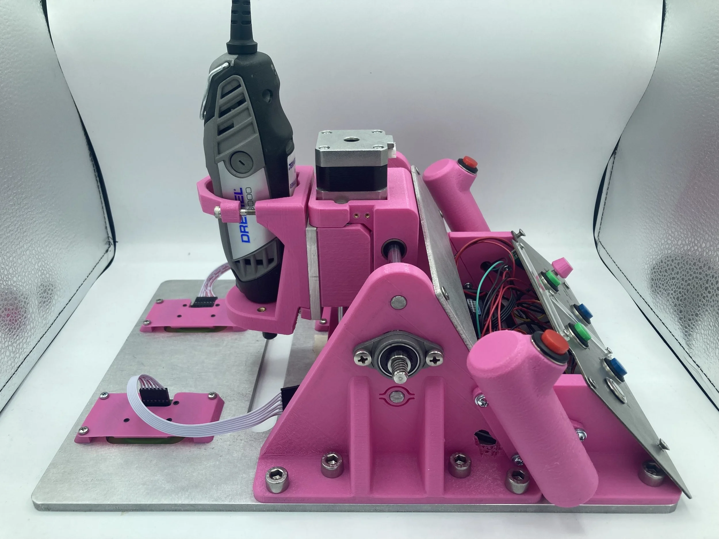
The main components of the assembly include a 3D printed body, aluminum waterjet base, 4 optical flow sensors, and 2 stepper motors coupled with lead screw gantries for actuation in two dimensions. All sensing, actuation, and control are handled with a single Teensy 4.1 microcontroller. Limit switches were implemented on both axes for homing the device. The main user inputs are two buttons that must be held down at all times when running (this ensures that the user in control of the device at all times. Otherwise everything stops immediately and the cutting bit is raised out of the workpiece). The homing and UI buttons can be seen in the figure to the right.
Main Components

Physical architecture of the device

Sensing
After brainstorming and experimenting with many different solutions for position sensing, I ultimately settled on the PMW3360 optical flow sensors for position estimation and control. These sensors are made for top of the line gaming mice, so they are highly responsive to small subtle movements, while also being capable of tracking large fast movements. This makes them perfect for our application.
Each sensor measures linear X and Y velocity, so position and orientation is calculated using rigid body dynamics and velocity integration. This induces a certain amount of drift over time, but was negligible for our purposes. In theory, two optical sensors would be sufficient for this calculation, but using four allowed us to average their results to reduce the error. This method resulted in an error of less than 3mm over a distance of 300mm. That level of accuracy was sufficient for our purposes, but further accuracy could be gained from filtering outliers, creating a closed loop sensing architecture, or implementing another filtering protocol.
The sensors are all mounted to the baseplate using “spring mounts”. Because the mice need to be a very specific distance away from the reading surface, these were designed to keep the mice pressed up against the workpiece so that the sensor is always the same distance away. This is better than a rigid mounting system because it can adapt to surfaces that are not perfectly planar. These mounts retain transversal stiffness, though, so the rigid body assumption with the baseplate still remains.

Spring mounts to ensure reliable readings from the sensors

Diagram showing how to determine where the spindle should move
XY coordinate system is the world frame
Line LR is the representation of the gantry
Point O is the position of the router - also the origin of the spindle (known)
Point B is the goal point (known)
Angle ∠B'OC is the angle or orientation (known)
OB' is the location to move the spindle (what we want)

Controls
To control the position of the spindle we first determine the next point in the inputted path for each time frame. This is found by calculating the closest point to the spindle that hasn’t been used yet. With both the position of the spindle and the goal point as known values (we get spindle position from the sensors and knowledge of stepper motor movement), we can determine how much we need to move the spindle using geometry. We also need to know the velocity the router is being moved at. The faster the user moves the device, the faster it has to respond to stay precisely on the path.
With these values, the spindle is actuated using PD control to reach the desired position with the determined velocity. This control needs to be implemented continuously through path so that it is always tracking the desired trajectory.
Electronics
All of our electronics were centered around a Teensy 4.1 microcontroller. We chose this microcontroller due to its large memory, high clocking speeds, and large number of I/O pins. This makes it perfect for the high frequency computations and controls we were implementing. It also is pre-compatible with SD cards which allows for very straightforward path loading.
Initially, everything was wired on a breadboard for easy prototyping, but this proved to be too unreliable for high frequency readings and high voltage motor controls. Everything was transferred to protoboards, though I included header pins and IC connectors for our main components so that they could detach while still maintaining a solid electrical connection.
Manufacturing
The hardware consists of 3D printed parts, a 1/4” waterjet aluminum base, laser cut sheet metal panels, optical flow sensors, and stepper motors that are all integrated using linear motion parts, nuts, bolts, and heat set inserts. The linear motion parts were first put together by my group-mates so that we could test the stepper motors. I’m glad we did this early on, because the stepper motor development was very buggy and time consuming.

The first sensor tests were actually me taking apart old computer mice and “hacking” the values from their sensors. This was a nice proof of concept to make sure that this method of sensing could work. I 3D printed a sled for the sensor too so that I could run it in a track of an exact distance and determine the quality. Even with decades old mice, the readings were still relatively precise and repeatable, so we decided to move forward with more expensive sensors. After I got the new sensors working individually, I made a jig to test 4 sensors together. This was used to check how well position and orientation measurements were tracked.


After all the parts were tested and working individually, the CAD was done, and the parts were printed, everything was assembled.


Future Improvements
So far, we have only cut with softer materials such as corkboard, MDF, and plywood. There are limitations that comes from using a low power Dremel as a router which make cutting harder materials a lot, well, harder. Hoping to experiment with hardwoods, plastics, and even metal (though will need enclosures for the electronics) in the near future, to try to push the Dremel to its limits. Once that is found, it would be great to throw on a more powerful router.
Other things include improving the UI to make the movement instructions more intuitive as well as improving the path planning algorithm to allow for more complex designs.